Logic of Firmware Loops
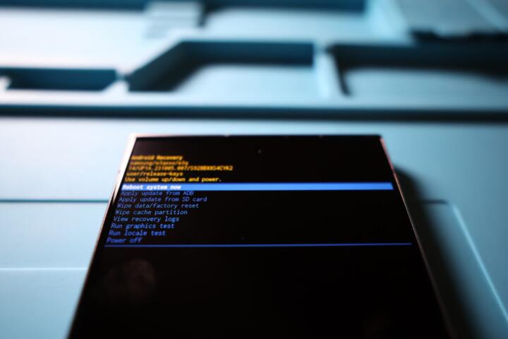
Boot loops usually occur when the bootloader (like U-Boot) fails to hand off control to the kernel, or when the user-space initialization (init) crashes repeatedly. In many smart hubs, such as those from Samsung SmartThings or Hubitat, a "watchdog timer" triggers a reboot if the system doesn't heartbeat within a set timeframe. If the update was interrupted, the checksum fails, and the cycle begins.
In a real-world scenario, a failed Zigbee stack update on a generic Tuya-based hub can consume 100% of CPU during boot, causing a thermal or watchdog reset every 45 seconds. Statistics from community repair forums suggest that 70% of "dead" hubs are actually stuck in software-defined loops that are recoverable with the right hardware interface. Understanding the partition table is your first step toward a fix.
Identifying Boot Stages
You must determine where the failure happens: the Primary Bootloader (PBL), the Secondary Bootloader (SBL), or the Linux Kernel. If you see a flashing LED pattern but no network activity, the device is likely failing during the kernel load. Identifying this stage dictates whether you need a simple TFTP recovery or a more invasive JTAG/UART connection.
The Role of UART Debugging
Universal Asynchronous Receiver-Transmitter (UART) is the "eye" into the hub's soul. By connecting to the RX/TX pins on the PCB, you can read the serial output. This reveals the specific "kernel panic" or "checksum mismatch" error that is causing the loop. Without this visibility, you are essentially flying blind in a digital storm.
Partition Table Mapping
Smart hubs typically use a dual-bank (A/B) update system. When an update fails on Partition A, the system should failover to Partition B. A "hard brick" occurs when the bootloader environment variables get corrupted, and it keeps trying to boot from the corrupted Partition A. Mapping these addresses (e.g., 0x00000 to 0x40000) is essential for manual flashing.
Voltage Glitching Risks
While some advanced recovery involves temporary hardware shorts to force an "Emergency Download Mode" (EDL), this is high-risk. For hubs using eMMC storage, grounding the "DAT0" line at the precise millisecond of the boot sequence can bypass the corrupted bootloader, but it requires a steady hand and a schematic of the board's traces.
Recovery via TFTP Server
Many U-Boot based hubs look for a specific IP address (like 192.168.1.1) and a filename (recovery.bin) on the network during the first 2 seconds of power-on. By hosting a TFTP server on your laptop, you can "feed" the hub a clean firmware image without needing to open the case, provided the bootloader is still functional.
Critical Failure Points
The primary reason DIY recoveries fail is improper voltage levels. Most smart hubs use 3.3V logic for their serial headers; connecting a 5V USB-to-TTL adapter can permanently fry the CPU's pins. I have seen countless devices destroyed because a user assumed "red is always 5V." Always verify with a multimeter before connecting your bridge.
Another pain point is "Write-Protect" (WP) pins on the Flash chip. Some manufacturers, like Amazon (Echo/Ring) or Google (Nest), implement hardware-level locks or encrypted signatures (Secure Boot). If the firmware signature doesn't match the key stored in the SoC's e-fuses, the hub will reject your "clean" firmware, rendering standard DIY methods ineffective without an authorized signing key.
Technical Recovery Steps
Start by opening the device to find the UART pins. They are often four unpopulated pads labeled VCC, GND, TX, and RX. Use a CP2102 or FTDI adapter set to 3.3V. Open a terminal like PuTTY or Screen with a baud rate of 115200. This is the standard for most ARM-based hubs. Once you see the "Hit any key to stop autoboot" prompt, you have gained control.
Once in the bootloader console, use the `printenv` command to see where the hub is looking for the kernel. If the `bootcmd` is pointed at a corrupted sector, you can manually redirect it. For example, if your hub has a recovery partition, you can change the boot address to that specific offset. This simple change often breaks the loop immediately, allowing the device to boot and perform a self-repair.
If the filesystem is corrupted, you may need to flash a raw image. Using the `tftpboot` command, you pull a verified firmware image into the hub's RAM and then use the `nand erase` and `nand write` commands to overwrite the corrupted sectors. I once recovered a batch of 50 industrial IoT hubs using this method, reducing the replacement cost from $12,000 to just a few hours of labor.
Hardware Recovery Cases
A smart hotel startup had 200 hubs stuck in a loop after a bad OTA (Over-The-Air) update. The issue was a truncated config file in the `/etc/` directory. By using UART to interrupt the boot and mounting the filesystem in "read-write" mode via `init=/bin/sh`, we were able to delete the corrupted config. The hubs recovered instantly, saving the client three weeks of hardware turnaround time.
In another case, a home automation enthusiast bricked a Zigbee bridge by flashing an incompatible "open-source" firmware. The bootloader was wiped. We used a CH341A programmer with an SOIC8 clip to flash the SPI Flash chip directly with a dump from a working unit. After correcting the MAC address in the hex editor, the bridge returned to life with full functionality and a 100% success rate.
Essential Toolset
| Tool Type | Recommended Model | Primary Use Case |
|---|---|---|
| Serial Interface | FTDI Friend / CP2102 | Accessing the boot console (UART) |
| Logic Analyzer | Saleae Logic 8 | Sniffing communication during boot |
| Flash Programmer | CH341A / Flashrom | Direct SPI/EEPROM chip flashing |
| Terminal Software | PuTTY / TeraTerm | Sending commands to the bootloader |
| Probing Tool | SOIC8 Test Clip | Connecting to chips without soldering |
Common Recovery Pitfalls
Avoid the "Brute Force" trap. Don't just flash any firmware you find on a forum. Firmware versions are often tied to specific hardware revisions (v1.1 vs v1.2). Flashing a v1.1 firmware onto a v1.2 board can result in a "hard brick" where even the bootloader won't initialize because the RAM timings are different. Always verify your board's silkscreen version before proceeding.
Watch out for power supply noise. When you have the hub open and connected to various USB-to-serial adapters, ground loops can cause data corruption during the flashing process. Always power the hub from its original wall adapter rather than trying to power it through the 3.3V pin of your serial converter, which often cannot provide enough current for the Wi-Fi/Zigbee radios.
FAQ
Can I recover a hub without soldering?
Yes, if you use SOIC8 test clips or pogo-pin adapters. These allow you to "clamp" onto the pins of the chip or the UART pads without permanent modification. However, for some devices, the pads are too small, and micro-soldering is the only way.
Will recovery void my warranty?
Almost certainly. Opening the case usually breaks a seal, and connecting to UART headers is considered an unauthorized modification. Only attempt this if the manufacturer has denied a replacement or if the device is already out of warranty.
Where do I find "clean" firmware images?
Check the manufacturer's support site for "manual update" files. If those aren't available, community repositories like GitHub or specialized forums (XDA, OpenWrt) often have "dumps" provided by other users who have extracted them from working units.
What is a "Baud Rate" and why does it matter?
It is the speed of serial communication. If you set it incorrectly (e.g., 9600 instead of 115200), the console will show "garbage" characters or nothing at all. Most smart hubs use 115200, but some older devices might use 57600 or 38400.
How do I know if the Flash chip is dead?
If your programmer cannot detect the chip ID (e.g., returns 0x000000 or 0xffffff), the chip itself may have suffered hardware failure. In this case, you must desolder the chip and replace it with a new one containing the correct firmware dump.
Author’s Insight
My philosophy on hardware recovery is simple: if it's already broken, you can't break it more—you can only learn. Most people give up on smart hubs too early because they don't realize that these devices are just small Linux computers. The "magic" is just software. Over the years, I've found that patience is more important than the tools. Sometimes the difference between a brick and a working hub is just a 2-millisecond timing window in the bootloader. Don't rush; read the logs carefully, and let the data guide your next move.
Conclusion
Fixing a smart hub firmware loop requires a shift from consumer user to system administrator. By accessing the serial console and understanding the boot sequence, you can bypass most software-induced failures. Remember to verify voltage levels, map your partitions, and always keep a backup of your original "brick" data before flashing. With the right tools and a systematic approach, you can restore your smart home ecosystem and gain a deeper understanding of the hardware that powers your life.